Location: Tübingen, Germany
“The CMS consists of an industrial robot arm with 6 independent axes, extended with an L-shaped cabin axis. The seventh axis allows for varying the orientation of the cabin with respect to the robot arm by changing the location of the cabin’s attachment point from behind the seat to under the seat, or any intermediate position.
Recently, the CMS has been further extended with a linear axis of 10 meters. The resulting 8 degrees-of-freedom (DOF) provide an exceptionally large workspace. Several extreme motions and positions can be achieved, such as large lateral/longitudinal motions, sustained centrifugal motions, infinite head-centered rotation, and up-side-down motions.
To ensure the synchronous motion of the robot axes and the external axes (cabin and linear axis) custom software was developed. This software combines/distributes the signals coming from/going to the respective axes while making sure all timing requirements are met.
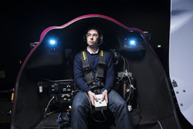
The cabin (including the cabin axis) was custom built, and allows for mounting a range of different input/control devices:
-
- Button boxes (custom built)
- Pointing devices (custom built)
- Car steering wheel and pedals (Sensodrive GmbH)
- Helicopter collective (Wittenstein aerospace & simulation GmbH)
- Helicopter cyclic (Wittenstein aerospace & simulation GmbH)
- Side-stick (Wittenstein aerospace & simulation GmbH)
The cabin is equipped with a stereo projection system (eyevis GmbH) with a field-of-view (FOV) of 140ºH x 70ºV and a resolution of 1920 x 1200 on each projector. High fidelity 3D visualization can be achieved with projection filters and glasses (Infitec).
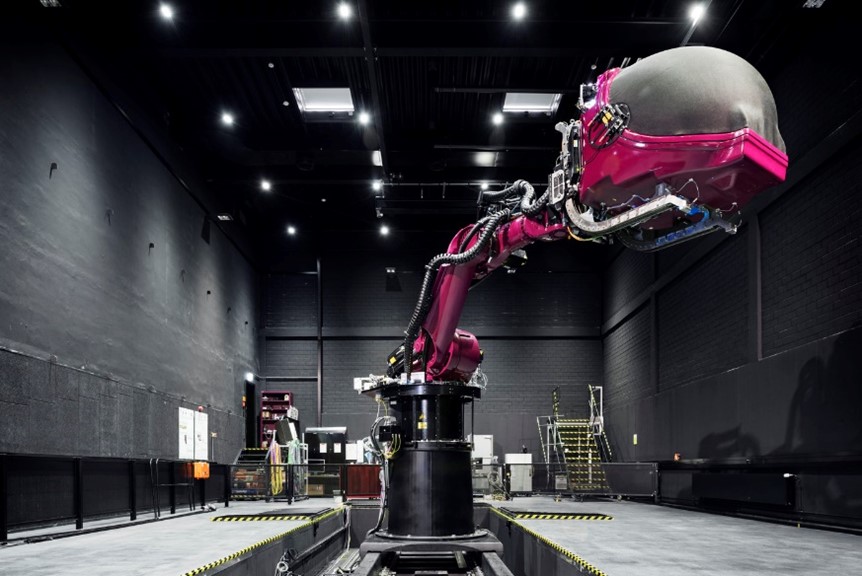
The Max Planck Institute for Biological Cybernetics CMS and its cabin
Source: Motion perception & simulation, Max Planck Institute